DIPLEXER TO FEED THE LNB,
THE WIDE BAND AMPLIFIER DETECTION
AND POST-AMPLIFIER
TO REPLACE THE SATFINDER
THE DIPLEXER
This small assembly is used to feed the lnb .
The lnb is fed by the coaxial cable which comes
from the demodulator.
The construction is very easy : on a small double side epoxy board
thickness 1.6mm trace a microstrip line with a cutter. Software as AppCad found on AGILENT'S
web site will give you dimensions to be respected according to the substrate .Dc is brought
by a by-pass (1nF) through a small winding, two turns of 5/10 silver wire here,un condenser
blocks the supply voltage towards the if amplifier and directs it towards the lnb.
Le model photographed uses "N" connectors because it is the connector which we use, but
you can make less expensive by using a ' F' for the exit towards the lnb,and a small
3.5mm jack .The model shown is 3cm*3cm, is not critical. The condenser is a small smd
of 100pF .The box is made out of tinplate.They are known as Shubert boxes , but you can make
them yourself with tinplate which are welded . Opitec sells on line and delivers to residence..
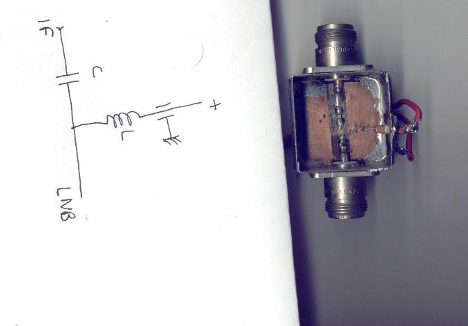
It can also be built using sma connectors.
THE IF WIDE BAND AMPLIFIER AND DIODE DETECTOR
The "satfinder" ,a generic term which now names these small cases that one finds easily
now to help with the alignment of the parabolas on the satellites are in fact broad band
amplifiers (1000 MHz -2000MHz in theory in fact much more, with great gain (40dbs at least),
associated with a diode and an operational amplifier with variable gain , a buzzer and a
galvanometer to measure the level of signal with an effect of threshold obtained by
feeding the galvanometer between two voltages one fixed and the other variable
depending on the received signal .The potentiometer of gain is often of doubtful quality,
and the gain so important that stability is at better ... bad ....
A radio astronomy receiver must be stable ,to solve this problem we built a small module
with some hybrid amplifiers (mmic) of mar6 type of Minicircuits and a diode Agilent hsms8202
assembled in a voltage doubler detector system.
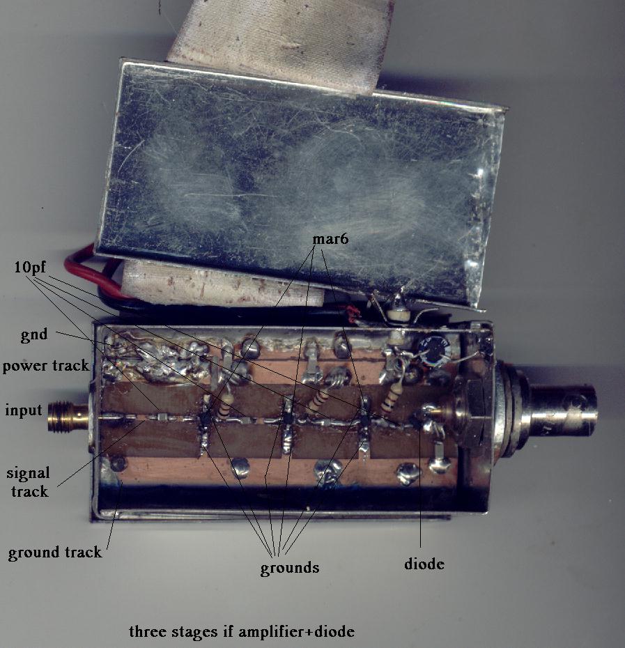
On the site of the manufacturers Mini-Circuits and Agilent you will find the relevant
application notes . Construction is very simple. As the assembly above it is articulated
on a 50ohms microstrip circuit of 6cm length, in a small metal case. This line is cut
to various places for the components. The power supply is brought through a feed-through
capacitor known as ' by pass' of 1nF. It is of 5v(regulator 7805).
This amplifier, followed by the post amplifier was tested successfully
(stability, reception of the thermal radiation near... tree, ground, beings humains..
pour sun in this moment - January 2006- it is necessary to wait...) with a satellite
lnb 11ghz and radio-link mixers of system 22ghz and 39ghz .
This small module that weight 30 grams can replace receiver USVD of R&S
that weights 30kgs .
Here is another specimen, photographed closely:
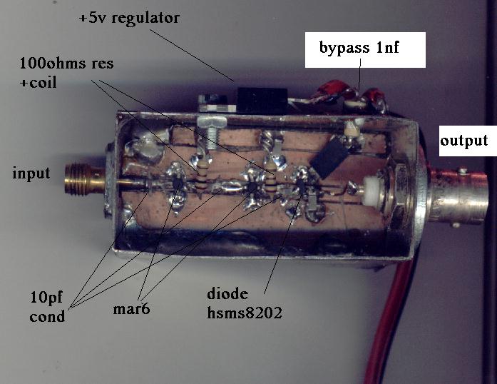
it includes two mar6, and a detecting diode
hsms8202 gone up out of doubling frame of tension. It is carried out simply, without
chemical manufacture of printed circuit: after realization of holes , welding of box
and bypass condenser , drilling for regulator (to take one 1 amp for avoid heat problems),
the plate from epoxy 16/10 is cut with the good dimension and two tracks are insulated
longitudinally, one for the 5v power supply and the other for the signal, this is done
simply with a cutter.Cut the signal track at the place of the components also. The crossings
of ground for the mar are made simply by boring holes with 0.5mm diameter and by welding
simple silver wire . Solder the case all around the circuit , excepted where the track +5v is.
Resistors at the output of the mmic are 100ohms must be imperatively carbon resistors (most frequent in fact),
because as their resistance increases with the temperature and the current which crosses them,
this effectively contributes to stabilize the mar6.The coils are three turns 2mm diam,made with
the wire of the resistor.
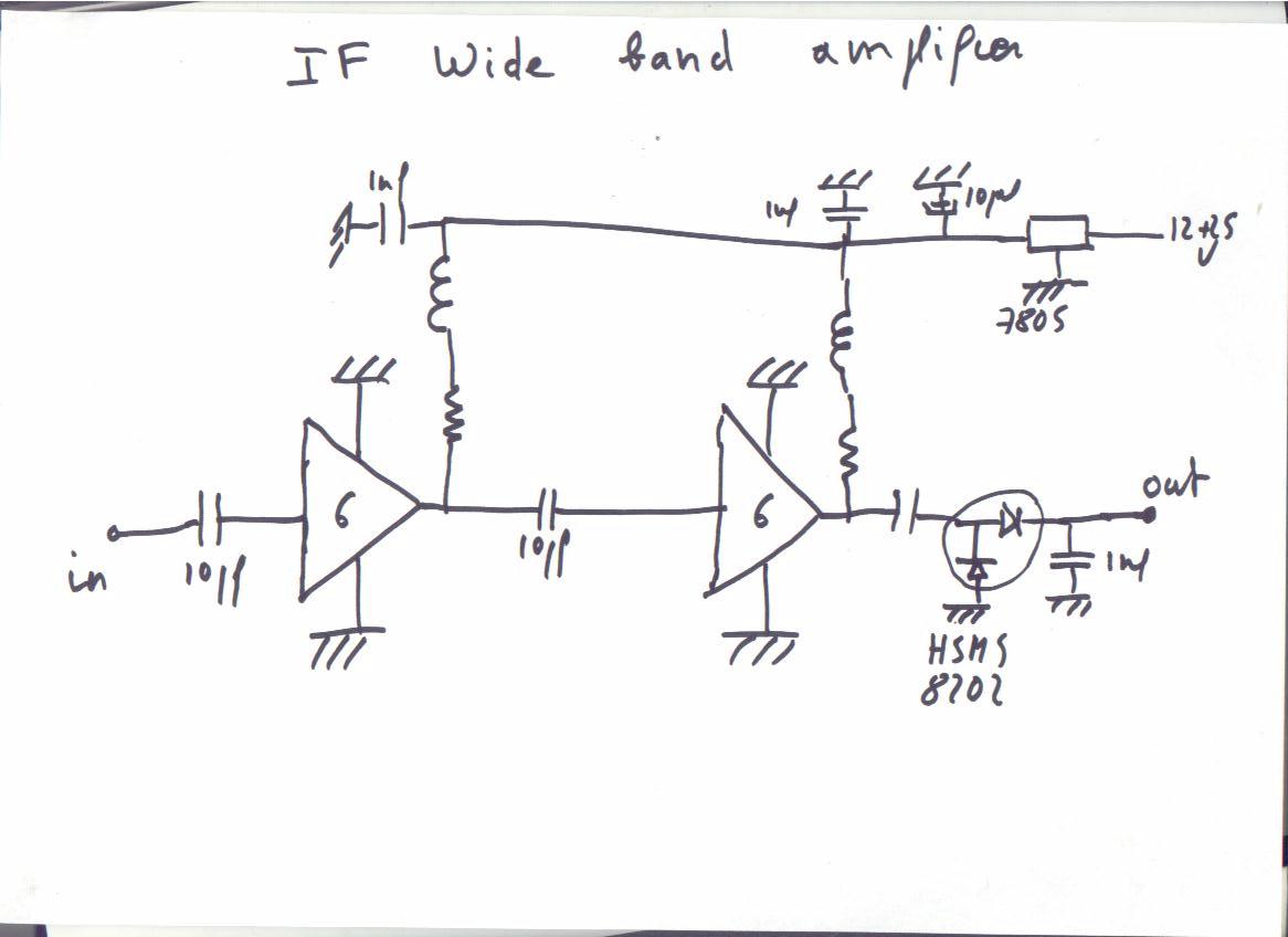
This assembly is also completely stable.
Several years ago the Elektor review had made a kit of a equivalent system ,
it is number 960041.
THE POST AMPLIFIER
It follows the detection and is used to adapt the received signal to the recorder PC or
chart recorder.
It is built with operational amplifiers op27 or op07 of Analog Devices . The assembly of
which you see the diagram below comprises two amplifiers the first carries out a dc
offset ,that makes a subtraction between the total noise resulting from the receiver
which includes not only the useful signal, resulting from the stars, but
also the basic noise manufactured by the receiver, et a variable tension by the multi-turn
potentiometer of 100k. This tension can be brought very close of that provided by the noise
of the receiver. There remains the useful signal .
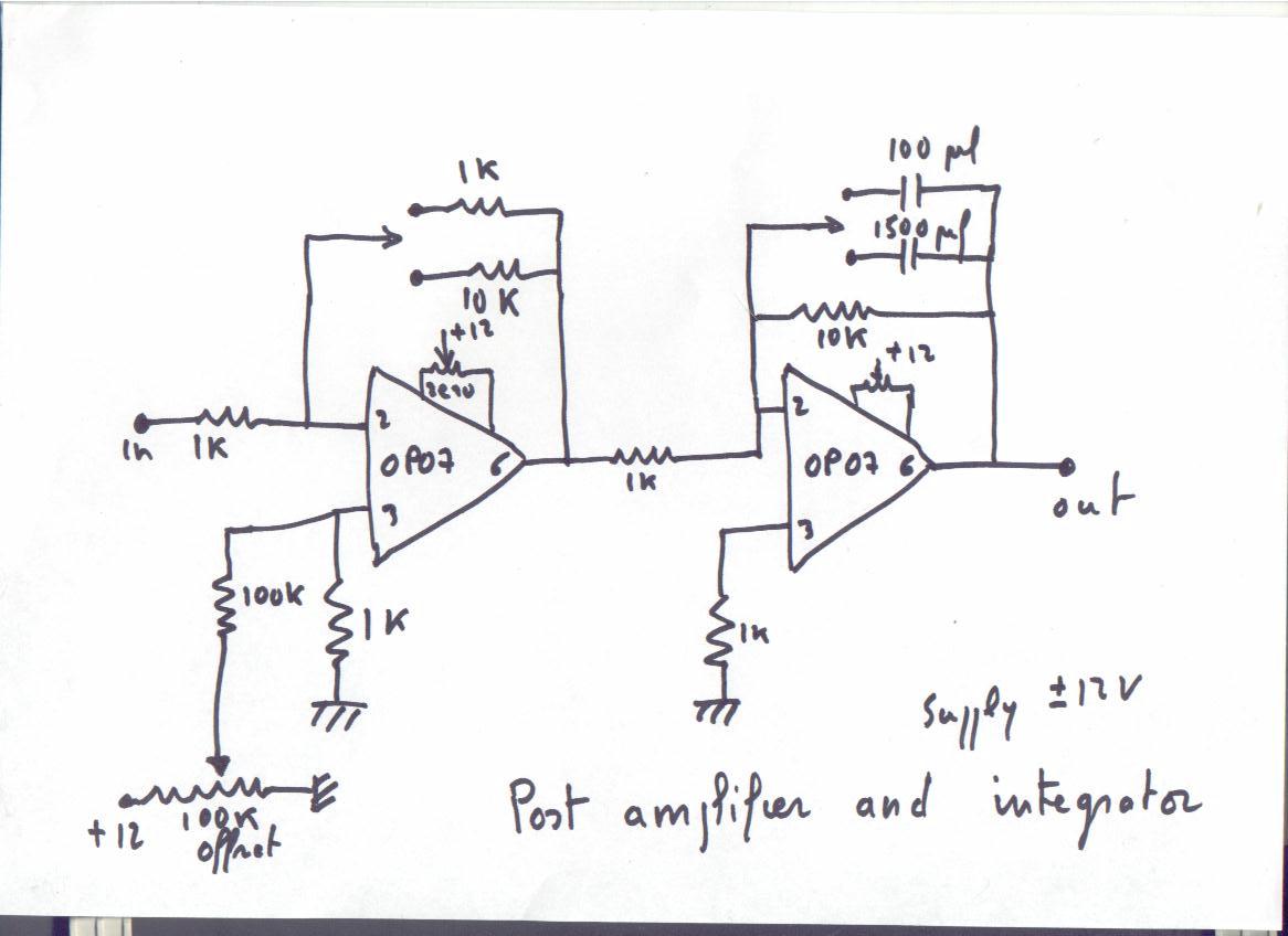
This first amplifier provides also a gain of 1 and 10 on the assembly, but which could be
100 or 1000, by changing the resistors connected to the amplifier.
At his output there is thus to it (total noise of the receiver - the reference)*gain. The second amplifier is
an integrator whose time-constant is 1 second or 15 seconds, with the values given but
which can be what one wants according to the value of the condenser.
This assembly can be made on a small plate with holes, no need to make printed
circuit. Resistors must be preferably metal resistors , avoid ordinary
carbon resistors , which would do a drift according to the temperature
(you want to measure the sun not the temperature of the room where are the stations...)
The amplifiers must be assembled on support, that facilitates servicing.
The 100k potentiometer is multi-turn of very good quality, it determines in very great
part the stability of your system. Power supply +-12 v, a few milliamperes .Decouple
by 0.1 microfarads. Each amplifier has its adjustment of zero by small multi-turn
potentiometers, ordinary ones here.
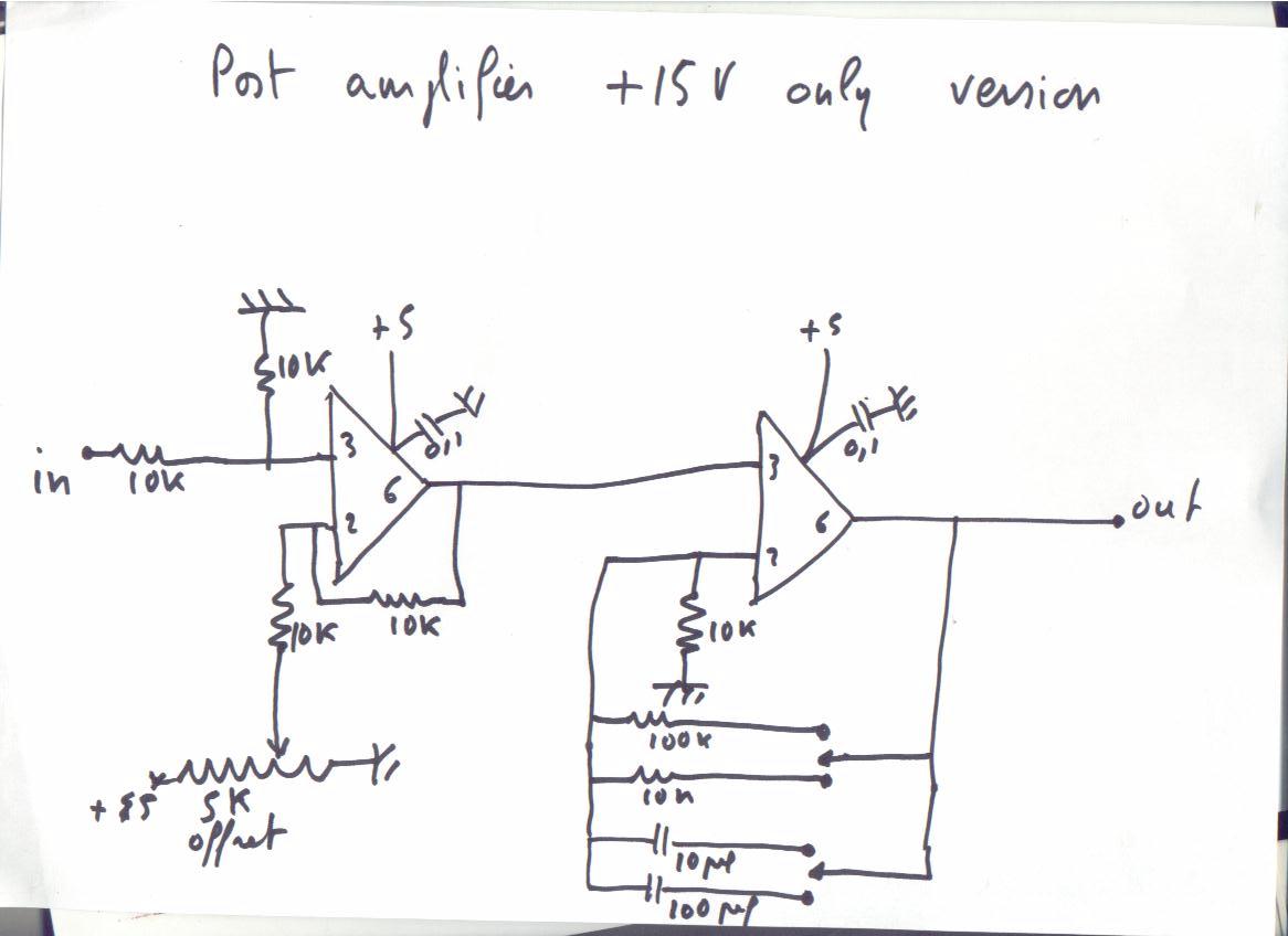
Here a version where the operational amplifiers (ad820 of Analog Devices) are supplied
only with + 5v.
In this assembly the 1st amplifier carries out the offset, 2nd amplification and integration
with the values given one has a total gain of 2 with a 0.1 second integration and 1 second,
a gain of 20 with an integration of 1 second and 10 seconds. All these values can be
modified according to your needs.
The printed circuit,
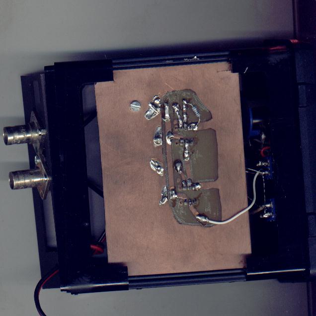
drawn by hand with varnish, on epoxy 16/10 double face copper (shielding), not bakelite
please . To limit the thermal drift of the assembly all resistors are metal layers
resistors , here no carbon resistor. For the power supply use one 7805, well decoupled,
decouple also the power supply at each amplifier by a 0.1µF.
These amplifiers are sufficiently precise so that the potentiometers of zero are useless.
The potentiometer ' zero' (offset) of 5k is multi-turn of very good quality.
And here is the finished assembly...
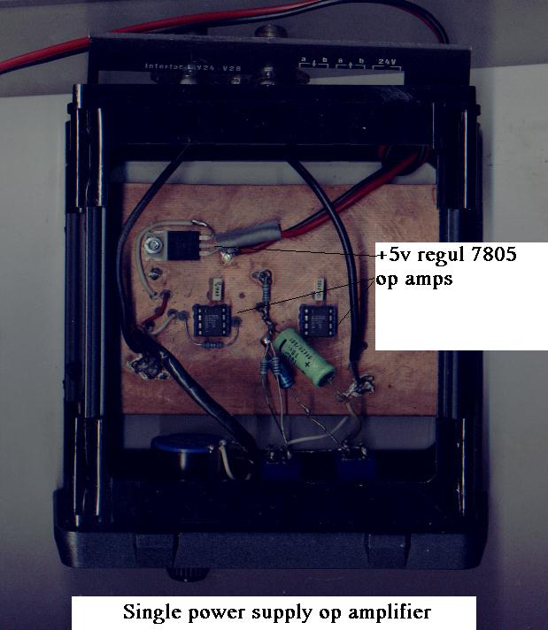
All the components of these assemblies can be found easily at electronic stores .
I remind to you that Analog Devices gives samples nicely, thank you!!!
Power for all that:
For the versions using our last assemblies only one alim +15v is enough...
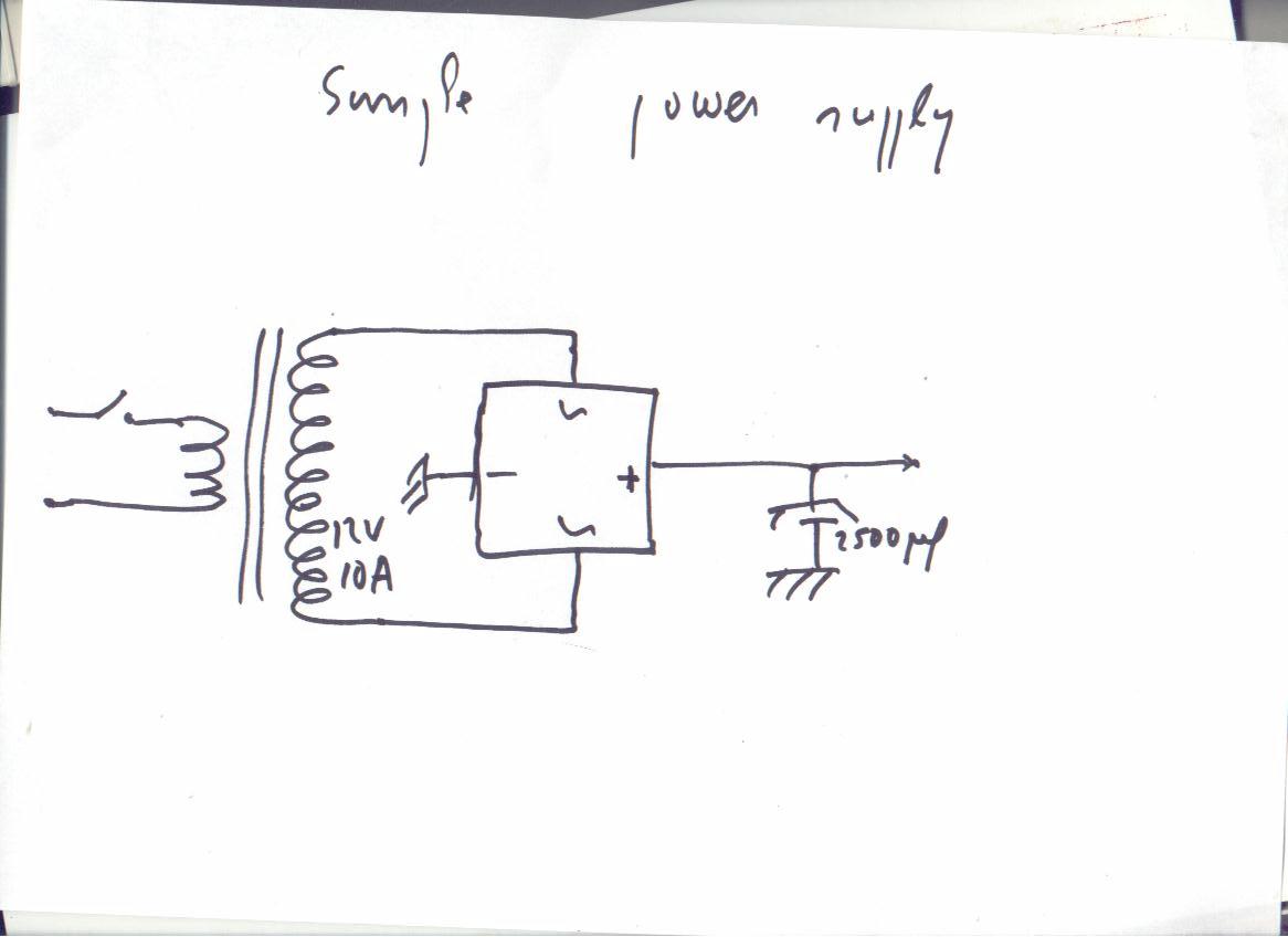
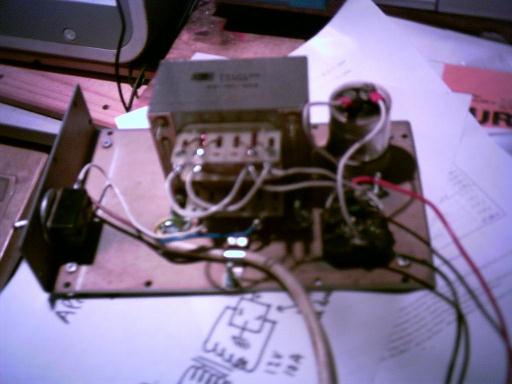
Here a diagram of a not regulated 15v power supply , traditional one using a transformer,
the regulations is done on the level of each module by integrated regulators of series 78.
Do not use a switching power supply , as those which one finds on the PC, they radiate,
even well shielded and can thus cause interferences.
The schematic and the photograph :
Well folks ,I think all this well help you in spending the winter on a useful way !!!
All this to show you that simple things can be made without sophisticated tools .The only
radio-amateur tool needed is a multimeter ...and a soldering iron .And evolution is possible
,as I mentioned I used this system on other frequencies...you can find lnb on 4ghz
(satellite band) ,22ghz ,and 40 ghz (radio-links) ,and it is sensitive enought
to think about building an interferometer .Radio astronomy is an endless story.
To help you in tracking the sun I enclose soltrack.bas
a simple program in basic .
And here is a FAQ .
BACK


