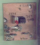
Here is an interesting plan whose principle was given to us by
Mr MONTIGNAC, of FLOIRAC.It is very stable thanks to the use of the OP27.

And the photo of one of our realizations, simple quadratic detector, with an
gain of 1 and without integration.
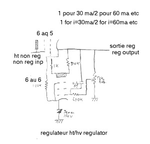
Here is the plan of hv regulators that we use in the 169 mhz sets as well on 1030 mhz.
(For those that would have forgotten this old technology...)
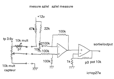
Here are the very simple sensors (site and azimuth) of the yellow parabola.
The measure is done by multiturn linear pots ( 10 turns), high quality, fed from the control box
. A pot of same quality adjusts their tension of supply at 3.6v (360mv / tour) .An op
amp( op27e ) in subtractor and allows to correct the possible errors of location of
the measure potentiometer, the other op07 has an gain of 1 adjustable to compensate for
the tolerances of components. The output is made on digital voltmeters, which show azimuth
from 0 to 360, and elevation of 0 in 90. The procedure of regulation is simple:
for every canal, with p1 adjust tp=3.6v. With p2 and the antenna in the North
(for the sensor az), or below (for the elev sensor) to adjust to have 0v in output.
With p3 to adjust to have 180mv in output (for the sensor az, the antenna being in the South),
or 90mv (for the sensor elevation the antenna being vertical).
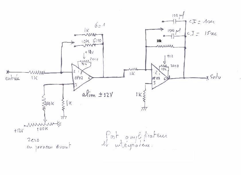
Here is the plan of the amplifier and the integrator built for the
1030 mhz receiver
in february 2001. He can follow the detector described above.
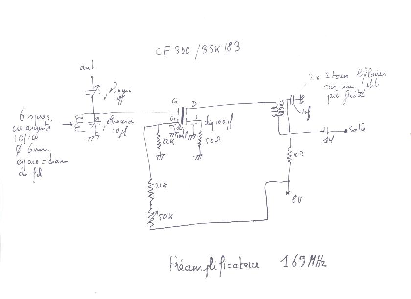
Here is the plan of the 169 mhz preaplifier.
And the photo of the one of them.
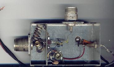
May 2007 : The cf300 is obsolete ,it can be replaced by bf988
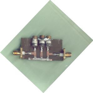
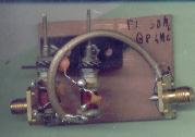
This is a small strip line filter over 1030 mhz, very useful when one use MMIC
to wide band amplifiers. The other filter is centred on 30mcs. This to show that it
is practicable, indeed is necessary to have what to measure them, either be helped.
