HOW TO BEGIN IN RADIO-ASTRONOMY ?
INTRODUCTION
Radio astronomy is a branch of astronomy , the science that studies the universe.
All the things that exist in the universe are at a physical temperature from very
low temperatures in deep space to milllions of degres in the middle of stars .
Plank's law says that every body emits noise according to it physical
temperature . What is called noise at this moment has nothing to do with the noise made by your neightbours ...,
it is an electric signal of random nature : random frequency , random
amplitude , random phase , it is what you ear on your radio receiver when there
are no radio transmittters . The frequency of this noise from thermal origin (one of its origin , the simplest but not the only one particularly about the sun ) , called thermal noise ranges from light and above to radio waves.
Radio astronomy is that part of science that studies the universe in radio spectrum that comprises
wavelenghts from millimetric waves (hundred of gigahertz) to very low frequencies (few kilohertz).
It is important to understand that thermal noise is everywhere in the spectrum ,
there is no particular frequency , you can 'listen' on the frequency you want .
But two things tend to moderate this:
* the athmosphere of earth acts as a filter , and some frequencies are absorbed by molecules of oxygen , water etc...
* Also unlike at the beginning of radio astronomy in 1930 , at that time there were very few radio
transmitters, now there are lots of uses of the radio spectrum , and official radio astronomy is done
only in several bands , like hydrogen band around 1420 mhz , where frequencies are (nearly) protected
from interferences , but for amateur use you do need to use them .
This so called cosmic noise can be received by any classic , reasonably sensitive , radio-receiver,
with a few dbs of antenna gain from shortwaves to uhf , maybe you did it without knowing you did...
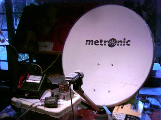
We will describe a simple , evolutive system , capable of receiving the sun at 11 ghz , but not only .
It will give you ideas to improve reception systems and , because of the modular description , many of the modules described here can be used on other frequencies , with other systems . All this is the result of real working things , it is the result of many years of work .
Three useful precisions for beginners :
There are differences , big differences between radio-astronomy and optical astronomy , essentialy radio-astronomy is very dependant from electronics , much more than optical astronomy is dependant from optics , I mean that , as there are no commercial radio telescopes , besides the ones produced by Radio Astronomy Supplies that are very specialised sets for hydrogen line , and are very expensive.
Every amateur radio astronomer will have to build and maintain its own radio telescope ,that is the reason why most of them are hams (I am f1gqb , ham since 50 years), it is impossible to do radio astronomy without a good knowledge in electronics , and really if some people cannot assemble a 11ghz lnb and a satfinder , it is better not to do radio astronomy and watch tv ... to help begin radio clubs exist .
At microwave frequency there is nothing particular in the waves produced by sun ,they are 99.999% of thermal origin . Solar bursts (linked with sun spots) happen in much lower frequencies ,vhf to uhf (100 to 1000mhz) , but building a set at those frequencies is difficult , here really no commercial solution exist you have to build your set , your antennas , everything , or modify a tv set for example , it is not easier.I did it , I built my own receiver , even an inteferometer , that worked well during 20 years and really here it is technical , not simple to build , not simple to maintain . There are lots of problems to solve for example lots of interference even in the 'protected' bands . It is for specialists in electronics ...
I'd like to add something about the differences of results
that amateur radio astronomers (solar or not) and amateur optical astronomers can have :it seems that human beeings are particularly sensitive to visual things, to images,in optical astronomy even for an amateur with a small telescope it is easy to get beautiful visual results : for example craters on the moon , satellites of jupiter or galaxies even with coulours
in some circumstances , there is nothing like this in amateur radio astronomy,the beautiful pictures you see in magazines are made by gigantic radio telescopes like the VLA with heavy computation done with some of the most powerful computers , an amateur will not have this , all that
he sees is the movement of the needle of a voltmeter or a chart recorder ,
maybe some fringes if he builds an interferometer , it is not possible to have pictures , such a project should involve a group of persons , with skills in electronics , computing etc...
who would not be amateurs .
In fact amateur radio astronomers can have now the results
that radio astronomers had in the beginning of
radio astronomy , let us say after WW2 .
It is not bad , it is interresting , but that is all that is possible , more needs big budget !!!
After all that , let us begin...
CHAPTER 1: SIMPLE SYSTEM
Let us say that such descriptions already exist on the Internet and that our assembly does
not have any originality . This assembly can interest a beginner by his simplicity or a
club of astronomy or a professor within the framework of a manipulation in electronics.
It is very evolutive , starting with a system that can be installed in a few minutes
but with lack of stability and sensitivity ,up to a very stable and sensitive system
with a computer controlled data acquisition system .
The basic system consists in a satellite tv reception system without any modification.
Le lnb receives radio waves between 11 and 12 ghz and transforms this frequency band into a
frequency band covering 1 to 2 GHz. In the case of the satellite reception,
the precise frequency of reception is fixed by the demodulator. A' Satfinder' is
put in the coaxial cable.
The Satfinder is a small tool used in the beginning to locate the satellites.
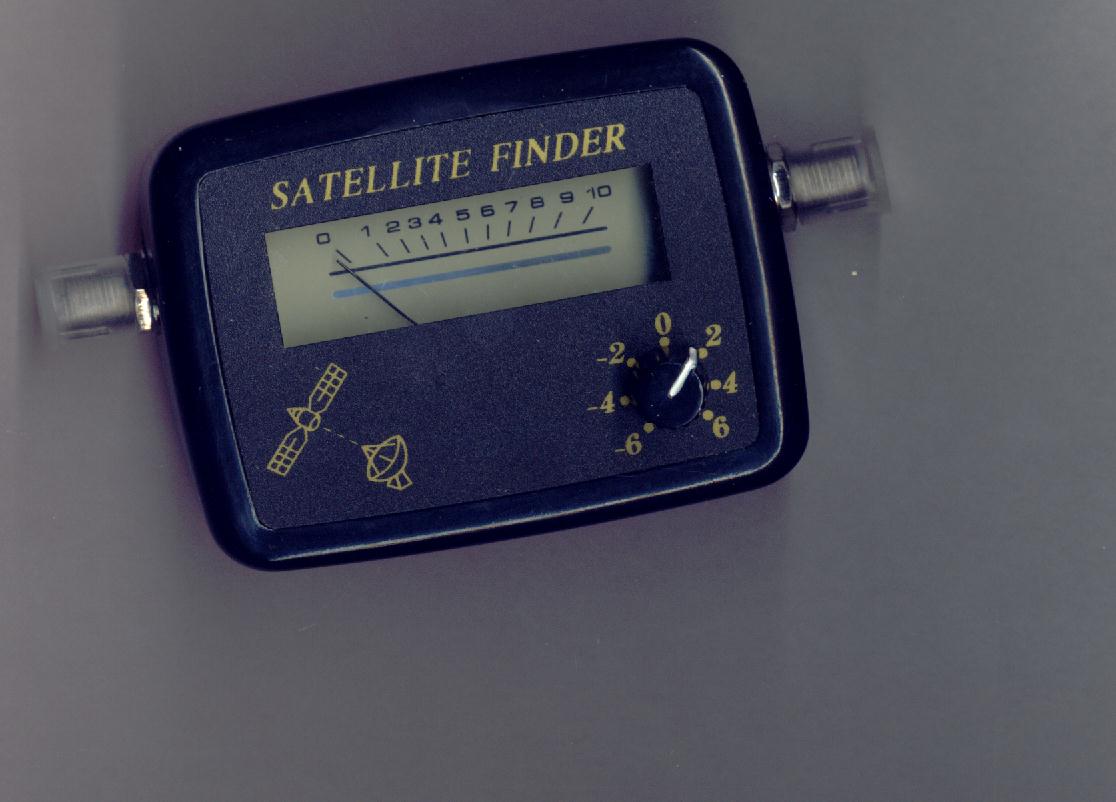
It is a wide band amplifier that receives between 1 and 2GHz and contains a detection
with a diode.
The maximum of the signal detected by the diode is indicated by the meter
that it contains and by a buzzer. There are various models, buy the least expensive...
and especially not the digital models.
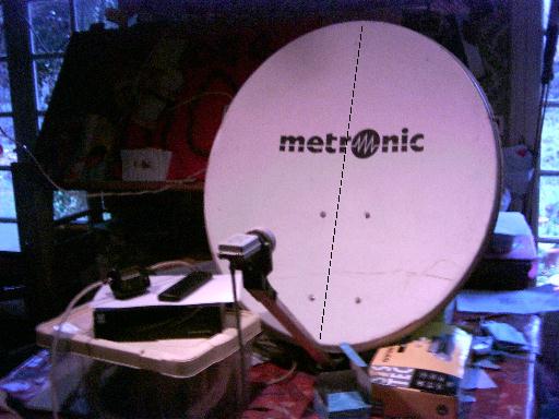
The connections are immediate: assemble the lnb on the parabolic reflector , an end the
coaxial cable with "F" plug is connected with the lnb, the other end this coax is connected
with the 'F' plug of Satfinder labeled ' to lnb', to the other "F" plug of Satfinder
connect another coax whose other end will go to the demodulator. This being installed,
power on the demodulator, regulate the small button of Satfinder until the needle moves a bit
when the antenna is directed to vertical far from any obstacle.
And by maintaining the shade of the sun in the vertical axis of the parabola, seek the
sun while sweeping upwards or downwards. Attention the precision of pointing is 1 degree
with a parabola of 90 cm. You found the sun? Very well. Note the position of the needle
of the modulation meter of Satfinder.
Now direct your antenna to the bottom, towards the ground and look : the modulation meter
indicates a very strong signal ??? What did you receive? Quite simply the radiation of our
planet, or more precisely the radio radiation of thermal origin. Without knowing it
or almost you come to observe two objects : our star and our planet. With your radio telescope
look around you, the trees, people, various places of the sky .According its temperature
any physical body emits something. At this frequency (11ghz) you receive waves of approximately
3 cm, but that occurs on all the frequencies. The light radiation is the same thing,
think of the color that has a piece of metal when you heat it: from brown ... red...
yellow... to bright white , it is similar. YOU just began in measuring the thermal radiation of the universe.
A receiver measures the thermal radiation of all that surrounds us, it measures the remote
temperature of it. It is a thermometer.
By measuring the temperature of the ground , you carried out
a calibration of your radio telescope because you can measure precisely the physical temperature with a thermometer . You have a well known level . Not too bad for a beginner!!!
Here are you have just entered the field of radio astronomy.
Thanks to the rather extraordinary electronic components that there is in a satellite
receiver which makes it possible to receive the emissions of TV of a satellite
at a distance 36000Km , the system which you have is much more sensitive than much
radio telescopes used at the beginning of the evolution of this science 60 years ago.
It suffers however from many problems , we will try to improve it.
First of all you have noticed that in this application the demodulator is used
for nothing else than provide dc power the Satfinder and the LNB , on the
' F' plug of the demodulator there is a dc voltage of 13-18 V which feeds the lnb
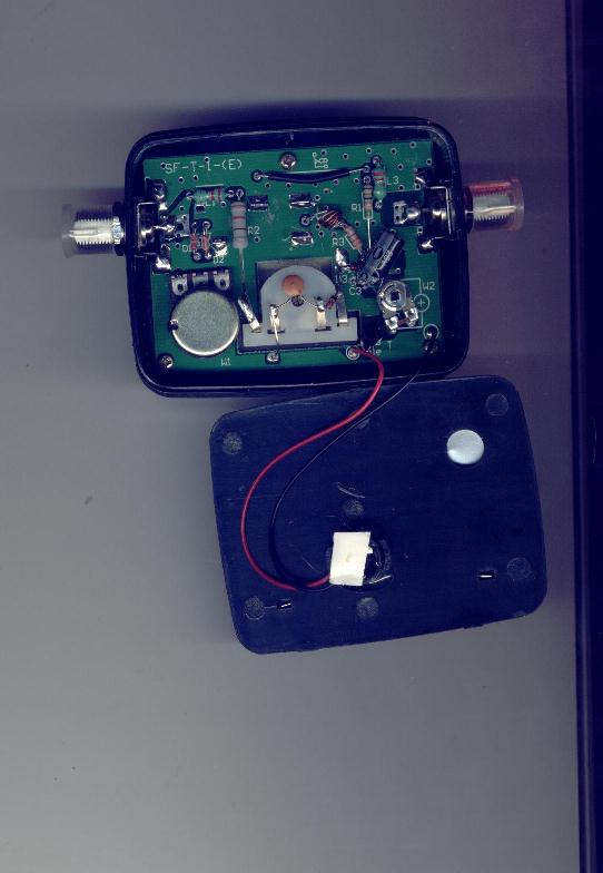
and Satfinder by the coaxial cable. The first modification will consist in opening Satfinder
and to solder two wires a black (ground) and a red (+) onto the ' F' plug marked ' to receiver',
the red is connected onto the center pin and the black on the adjacent ground . The wire is
outputed by a hole (cf images). Here are you can leave away the demodulator and replace it
by a small 15V 1A dc power suply well regulated . You can also use batteries to do
mobile radio astronomy...
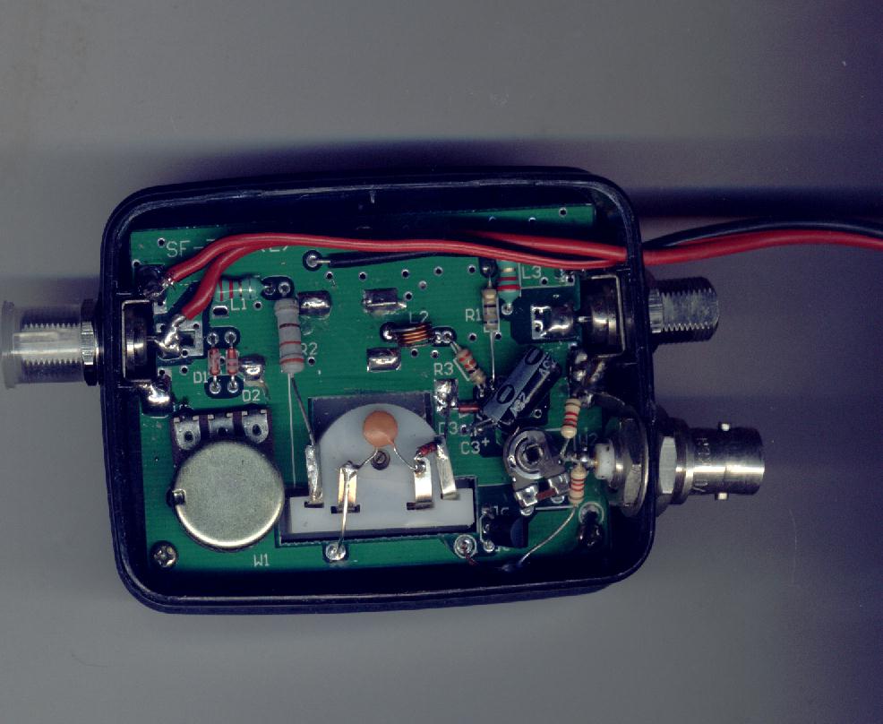
The second modification will consist in reading measurement on a measuring
apparatus more precise than the meter of Satfinder or to send it towards a system
of recording. For that locate the buzzer, there are two wires a red and a black.
The black is the ground and the red conveys a tension proportional to the received signal.
Cut two wires by leaving one or two centimetres . Remove the buzzer, you need
some more plug BNC or Cinch with the to output the signal. Between the two
wire red and black weld two resistances of 1.2k in series (= with the continuation one
of the other). The point medium of resistances is soldered with the center pin of the BNC.
The Ground of the plug is soldered with the black wire. Look at the photographs...
the tension of the buzzer proportionnal to the received signal is on the BNC. With
two resistances in series we divided it by two as it is too much for many systems of
recording.
On the bnc you can use now a digital voltmeter to have a precise measurement.
The complete system now includes a parabolic reflector, a lnb, a modified satfinder ,
a voltmeter and a power supply .
The cost of this assembly is very low . Do not hesitate to take benefit from the '
promotions . Parabolic reflectors with lnb is for 50 euros, a ' satfinder' for 10 euros,
a small universal controller is for 5E. For the 15v power supply kits exist.
This assembly presents limitations due to its simplicity. It presents primarily a lack of
stability related to several factors: lnb and satfinder not thus thermostated there is a
slow thermal drift, in the detecting satfinder with simple diode and not thermically
compensated, use of "F" plugs whose quality is not what is necessary to make radio
astronomy and general instability of Satfinder whose adjustment of gainis too precise .
Also as it is a broad band receiver it is sensitive to the signal of the satellites . It is
necessary that learn how to know where they are in the sky so that you do not get interference from them .
IMMEDIATE RESULTS : Monday 3/10/2005 we used this receiver with others (1440 MHz and 151Mhz)
to study the eclipse. It functioned well and thanks to him we could see a reduction of 50% of
flow on this frequency at the precise time of maximum eclipse. This shows what one knows :
on this frequency band what one observes in radio corresponds to the visible solar
disc in optics. The passage of the moon straight forwardly cut the beam of solar flow.
The phenomenon was very brute and fast .
Next how to replace the unstable satfinders.
CHAPTER 2 : DIPLEXER , WIDE BAND AMPLIFIER , DETECTION AND POST-AMPLIFIER
THE DIPLEXER
This small assembly is used to feed the lnb .
In the firts version , the lnb is fed by the coaxial cable which comes
from the demodulator.
The construction is very easy : on a small double side epoxy board
thickness 1.6mm trace a microstrip line with a cutter. Software as AppCad found on AGILENT'S
web site will give you dimensions to be respected according to the substrate .Dc is brought
by a by-pass (1nF) through a small winding, two turns of 5/10 silver wire here,a condenser
blocks the supply voltage towards the if amplifier and directs it towards the lnb.
Le model photographed uses "N" connectors because it is the connector which we use, but
you can make less expensive by using a ' F' for the exit towards the lnb,and a small
3.5mm jack .The model shown is 3cm*3cm, is not critical. The condenser is a small smd
of 100pF . The box is made out of tinplate.They are known as Shubert boxes , but you can make
them yourself with soldered tinplates . Opitec sells on line and delivers to residence..
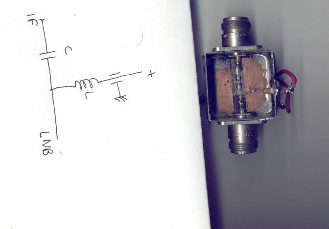
It can also be built using sma connectors.
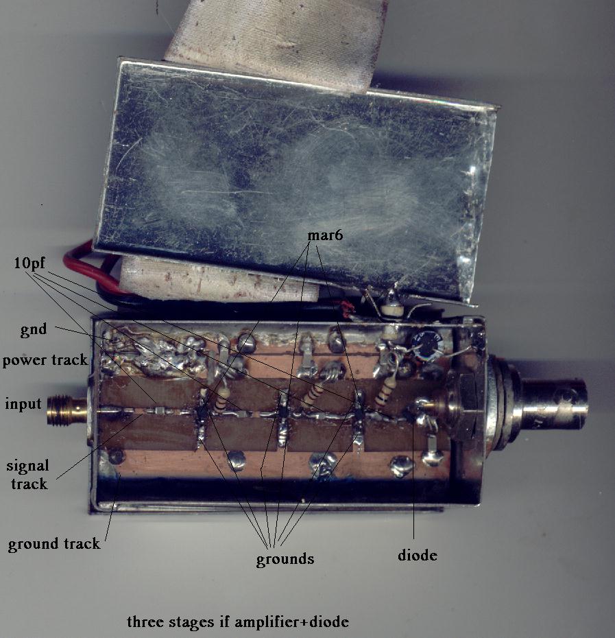
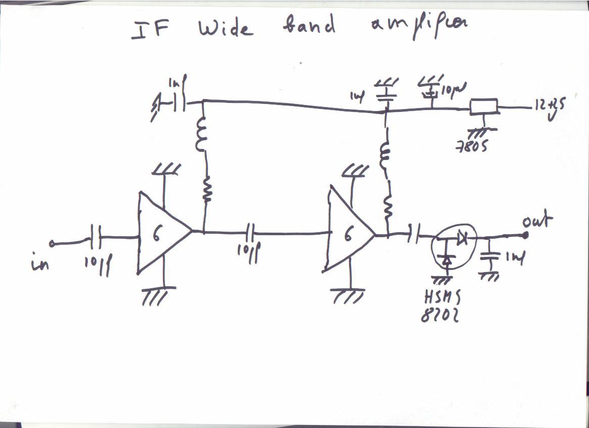
THE IF WIDE BAND AMPLIFIER AND DIODE DETECTOR
The "satfinder" ,a generic term which now names these small cases that one finds easily
now to help with the alignment of the parabolas on the satellites are in fact broad band
amplifiers (1000 MHz -2000MHz in theory in fact much more, with great gain (40dbs at least),
associated with a diode and an operational amplifier with variable gain , a buzzer and a
galvanometer to measure the level of signal with an effect of threshold obtained by
feeding the galvanometer between two voltages one fixed and the other variable
depending on the received signal .The potentiometer of gain is often of doubtful quality,
and the gain so important that stability is at best ... bad ....
A radio astronomy receiver must be stable ,to solve this problem we built a small module
with some hybrid amplifiers (mmic) of mar6 type of Minicircuits and a diode Agilent hsms8202
assembled in a voltage doubler detector system.
On the web sites of the manufacturers Mini-Circuits and Agilent you will find the relevant
application notes . Construction is very simple. As the assembly above it is articulated
on a 50ohms microstrip circuit of 6cm length, in a small metal case. This line is cut
to various places for the components. The power supply is brought through a feed-through
capacitor known as ' by pass' of 1nF . It is of 5v(regulator 7805).
This amplifier, followed by the post amplifier was tested successfully
(stability, reception of the thermal radiation near ... trees, ground , human beings..
sun with a satellite
lnb at 11ghz and radio-link mixers at 22ghz and 39ghz .
This small module that weight 30 grams can replace USVD receiver of R&S
that weights 30kgs .
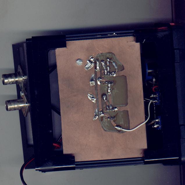
Here is another specimen , photographed closely :
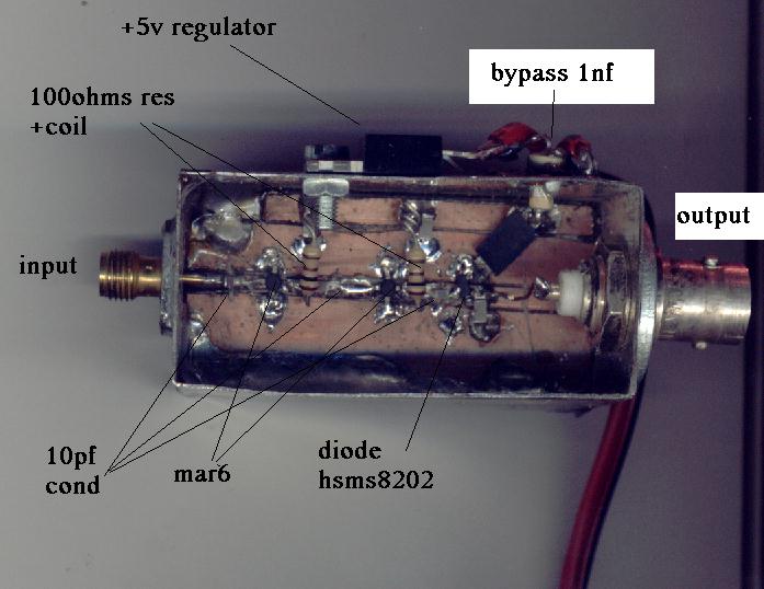
it includes two mar6, and a detecting diode
hsms8202 in voltage doubler . It is carried out simply, without
chemical manufacture of printed circuit: after realization of holes , soldering of box
and bypass condenser , drilling for regulator (to take one 1 amp for avoid heat problems),
the plate from epoxy 16/10 is cut with the good dimension and two tracks are insulated
longitudinally , one for the 5v power supply and the other for the signal, this is done
simply with a cutter.Cut the signal track at the place of the components also. The crossings
of ground for the mar are made simply by boring holes with 0.5mm diameter and by welding
simple silver wire . Solder the case all around the circuit , excepted where the track +5v is.
Resistors at the output of the mmic are 100ohms must be imperatively carbon resistors (most frequent in fact),
because as their resistance increases with the temperature and the current which crosses them ,
this effectively contributes to stabilize the mar6.The coils are three turns 2mm diam,made with
the wire of the resistor .
This assembly is also completely stable .
Several years ago the Elektor review had made a kit of a equivalent system ,
it is number 960041.
THE POST AMPLIFIER
It follows the detection and is used to adapt the received signal to the recorder PC or
chart recorder.
It is built with operational amplifiers op27 or op07 of Analog Devices . The assembly of
which you see the diagram below comprises two amplifiers the first carries out a dc
offset , that makes a subtraction between the total noise resulting from the receiver
which includes not only the useful signal, resulting from the stars , but
also the basic noise manufactured by the receiver, et a variable tension by the multi-turn
potentiometer of 100k. This tension can be brought very close of that provided by the noise
of the receiver . There remains the useful signal that can be amplified and integrated.
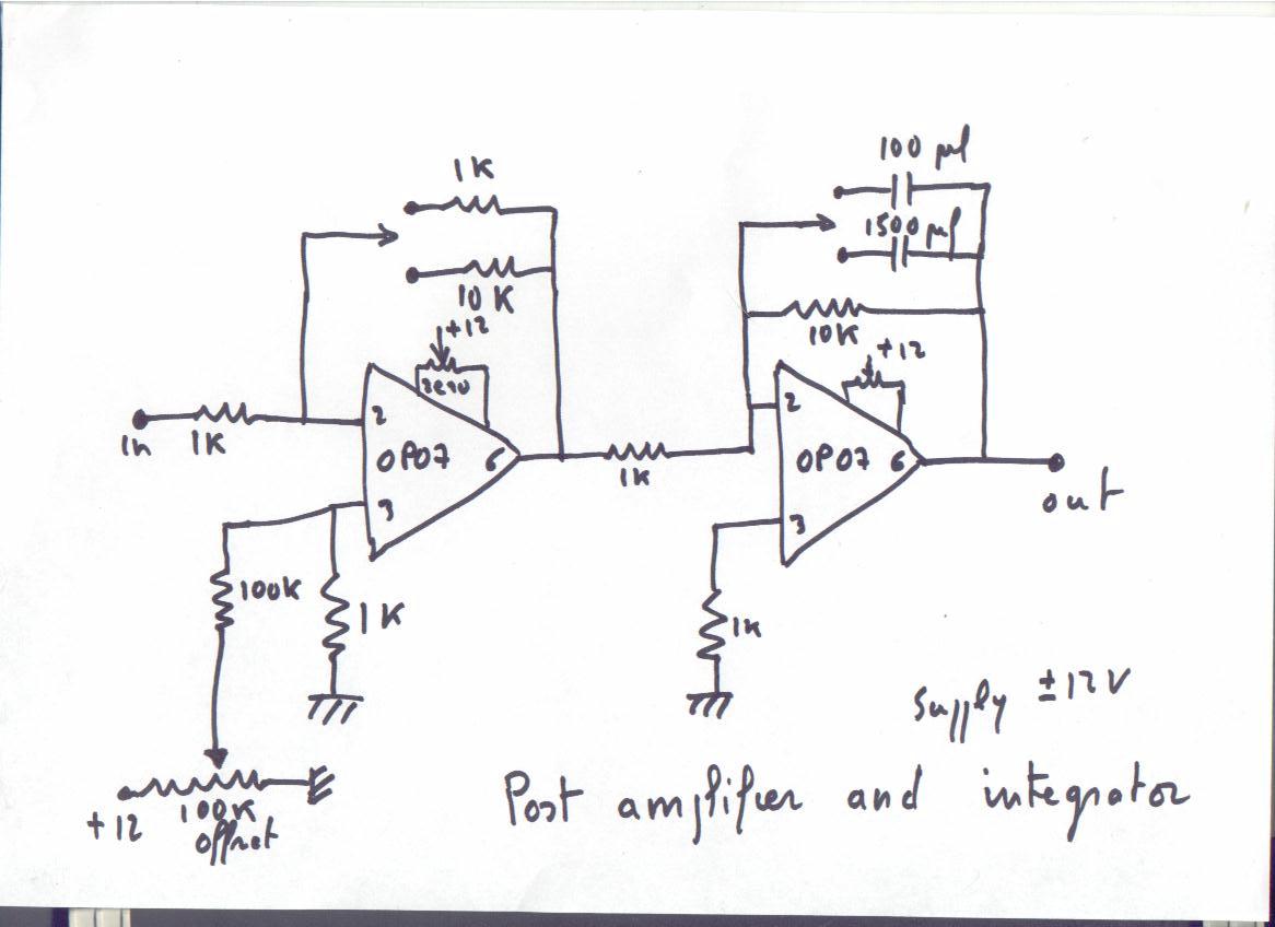
This first amplifier provides also a gain of 1 and 10 on the assembly, but which could be
100 or 1000, by changing the resistors connected to the amplifier.
At his output we get (total noise of the receiver - the reference)*gain.
The second amplifier is
an integrator whose time-constant is 1 second or 15 seconds, with the values given but
which can be what one wants according to the value of the condenser.
This assembly can be made on a small plate with holes, no need to make printed
circuit. Resistors must be preferably metal resistors , avoid ordinary
carbon resistors , which would do a drift according to the temperature
(you want to measure the sun not the temperature of the room where is the receiver...)
The amplifiers must be assembled on sockets , that facilitates servicing.
The 100k potentiometer is multi-turn of very good quality, it determines in very great
part the stability of your system . Power supply +-12 v, a few milliamperes . Decouple
by 0.1 microfarads . Each amplifier has its adjustment of zero by small multi-turn
potentiometers , ordinary pots here.
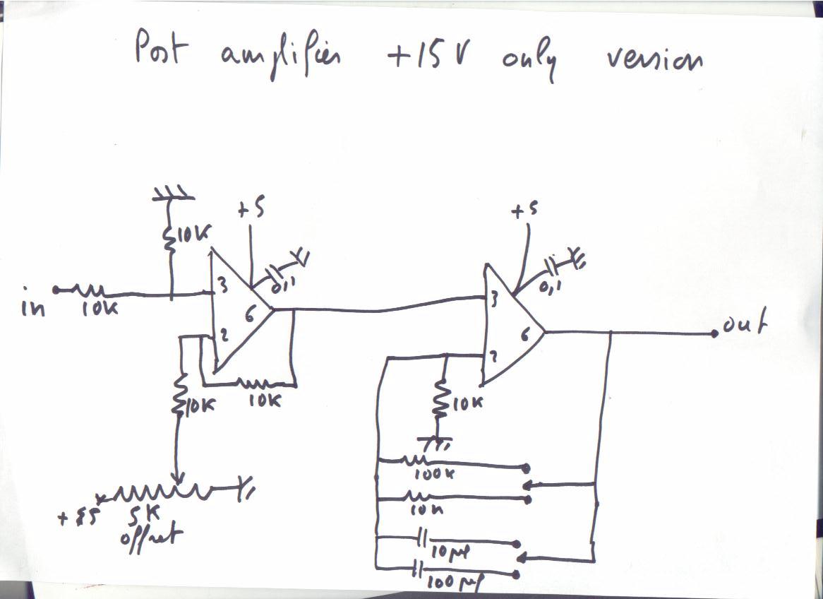
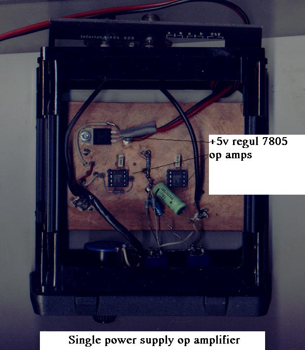
Here a version where the operational amplifiers (ad820 of Analog Devices) are supplied
only with + 5v.
In this assembly the 1st amplifier carries out the offset, the 2nd does amplification and integration
with the values given one has a total gain of 2 with a 0.1 second integration and 1 second,
a gain of 20 with an integration of 1 second and 10 seconds. All these values can be
modified according to your needs.
The printed circuit ,
drawn by hand with varnish, on epoxy 16/10 double face copper (shielding), not bakelite
please . To limit the thermal drift of the assembly all resistors are metal layers
resistors , here no carbon resistor. For the power supply use one 7805, well decoupled,
decouple also the power supply at each amplifier by a 0.1µF .
These amplifiers are sufficiently precise so that the potentiometers of zero are useless.
The potentiometer ' zero' (offset) of 5k is multi-turn of very good quality .
And here is the finished assembly ...
All the components of these assemblies can be found easily at electronic stores .
I remind to you that Analog Devices gives samples nicely , thank you!!!
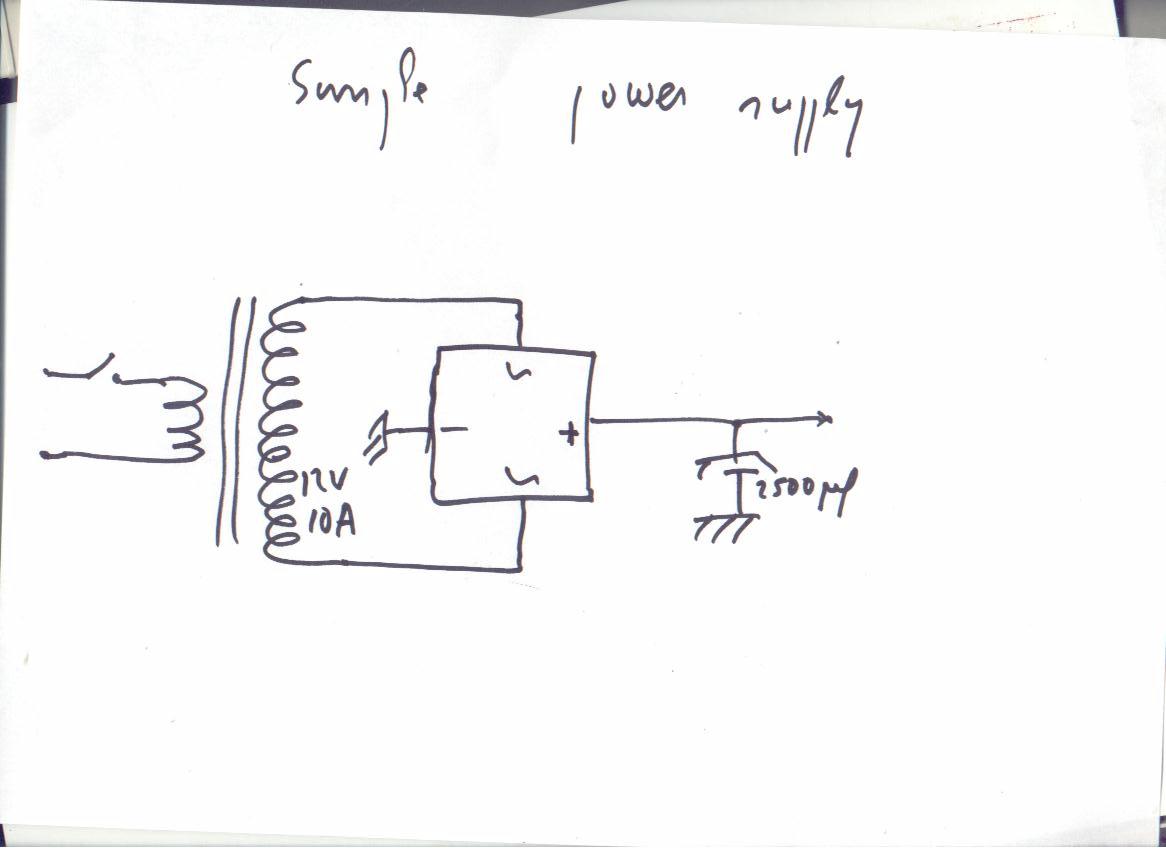
Power for all that :
For the versions using our last assemblies only +15v is enough...
Here a diagram of a not regulated 15v power supply , traditional one using a transformer,
the regulations is done on the level of each module by integrated regulators of series 78 .
Do not use a switching power supply , as those which one finds on the PC, they radiate ,
even well shielded and can thus cause interferences.
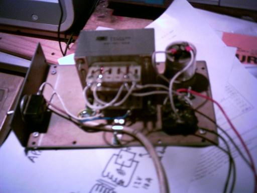
The schematic and the photograph :
CHAPTER 3 : DATA ACQUISITION
Thanks to the kind assistance of MAXIM company which we thank here, and which sent to us
a few samples , we started to carry out what we considered for a long time : digitalization
of the received signals .
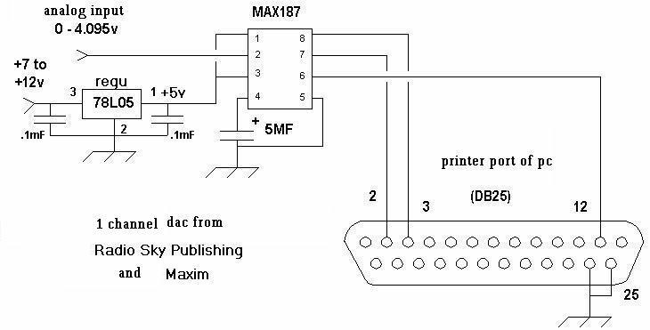
We built a small a/d converter with one channel with a max 187 according to the
model described on the site of Radio-sky publishing . This system uses the printer port of a PC .
We use an old HP VECTRA with 33mhz clock that is not expensive and does not put interference
to the receivers , any pc with dos can do the job .
Here is the schematic :
We wrote the programs in qbasic to make measurements : one which does data acquisition, records measurements
and records them on the disc, and another program which reads a file already recorded.
The recorded files include the number of the measurement, the measured value
and the hour according to the hour of the PC. This file is in ASCII, its name is formed
from the date, and it can be read by any standard editor . It can be used with
free software like GNUPLOT, after one very simple modification by a standart editor
to replace the commas which separate the data (it is standart in any sequentially recorded file)
by a space necessary for the reading by Gnuplot . The speed of acquisition is variable
even during the acquisition, the reading rate also , and the two speeds are independent.
One can be used to do acquisition very quickly , until 100 measures/second on a fast PC , and read
again slowly .
Let us specify that the sub-routine of the program of acquisition is a modified version
of a routine published on the site of Radiosky publishing .
The two programs are :
to do data acquisition
to read previously acquired data
CONCLUSION
Well folks ,I think all this will help you in spending the winter on a useful way !!!
All this to show you that simple radio-astronomy can be made without sophisticated tools .The only tools you need are a multimeter and a soldering iron .
And evolution is possible , as I mentioned I used this system on other frequencies ... you can find lnb on 4ghz (satellite band) , 22ghz , and 40 ghz (radio-links) , and it is sensitive enought to think about building an interferometer . Radio astronomy is an endless story.
To help you in tracking the sun I enclose a simple program in basic .