We began to use it with the first receiver of radar of our beginnings(front end mixer
30 mhz if).
The results were correct, but with many interferences due to the 27 mhz.
We got a 11ghz satellite front end , fed with 14 v regulated and used the 1030mhz receiver.
We built it in a solid system stand, with stabilized power supplies (hv and heaters),
and provided it with ventilators and used it behind the satellite head with very good results.
In September 1999, we replaced this receiver by the another one: a receiver who covers from
1600mhz to 2300 mhz from a surplus radio link made by THOMSON.
We removed all the transmitter parts , the coaxial relay and built a power supply with integrated regulators.
We modified a line amplifier ,changing connectors to sma and used it as rf amplifier.
The video amplifier and the integrator are described in the page ' ideas' of this site.
This set is put in a thermostated box and ventilated. It is to note that alone,
without preamplifier, and with 4m of feeder ( rg213 ), this receiver allows
to receive the sun in good conditions with the parabola of 3.3m on 1600mhz.
It was an attempt among lots... This receiver has been used a long time following the 11ghz front head to which it was
connected by 25 m of rg213 coaxial cable.In dec2001 this receiver has been replaced by the 1420 mhz wide band receiver
we built (cf " ideas " page ) .
The results are very correct, similar to those of the 169 mhz.
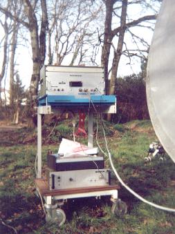
In Februray 2000, we reconstructed a receiver over 1030 mhz to follow the 3cm front end.
This receiver is with lamps and uses a very well stabilised power supply (less than 0.1 v
of variation on 100v). By adding a commercial line amplifier ( g=20b ), between the lnb and
the receiver the sensibility is very good (200 mv of variation of the tension of output
of the set when receiving the the sun), and the much better stability.
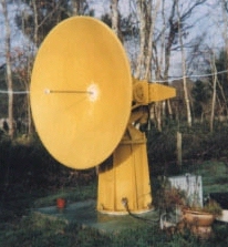
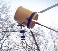
In February, 2001, we changed the illumination of the yellow parabola on 3cm for a
Chapparal source .The reception is fantastic. We have twice more signal of the sun.
And we were even able to receive the moon, approximately 15 times weaker as the sun.
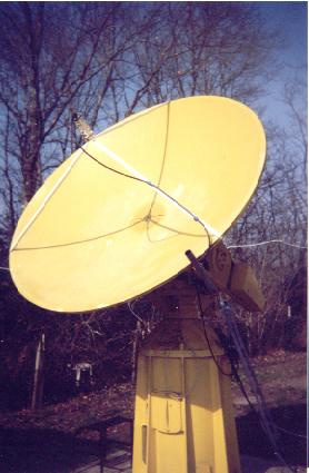
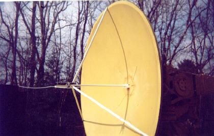
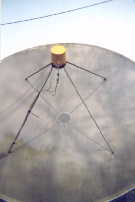
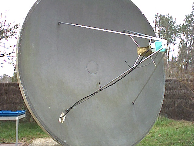
Here is how we installed the source in the focus. Having measured the diameter
and the depth, the focal length = ( diam*diam ) / (16*depth), a rod of correct length,
fixed temporarily, allowed us to position the source.
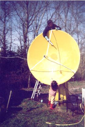
You see that all the family participates in the maintenance....
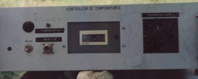
This receiver released from the 11ghz installation by the construction of the 2-nd 1030mhz receiver ,found now the parabola of 3.3m to be an autonomous systeme. In the input of the receiver, we put a coaxial relay which allows to replace the antenna by a 50 ohms load, which gives a point of absolute reference by simple measure of the temperature with the help of a small digital thermometer which also indicates the time:))) The preamplifier is in a plastic box filled with polystyrene and surrounded with a aluminised bubble paper. The temperature is reasonably stable.
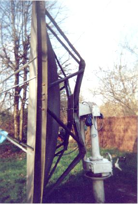
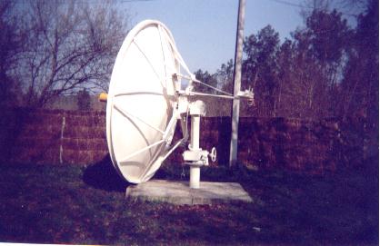
On February 2001: we added a counterweight to the grey parabola. It is 75 kg. It is fixed
simply by screwed bars. There is no weld. It is perfectly solid. And finally, the parabola
can be raised by a single hand.... The motorization is for the study.
Three photos to help you to understand.
It is to note that all this is very modular, we can use the 11ghz head with the
parabola of 2m either with the receiver 1030 mhz, or with the receiver 1600 mhz,
and use the parabola of 3.3m with the one or other one of these receivers.
We can also use the parabola of 3.3 m on 11 ghz. For that purpose we built
for this parabola quickly exchangeable sources on 1030 mhz, 1600 mhz,
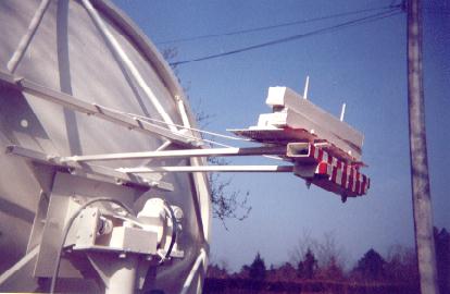
2300 mhz and 11ghz. At the end of jan 2002 we replaced all these sources by a unique
wide band source (1.2 to 2.4 ghz) described in DUBUS (2/86) by Peter RIML .This horn was tested
on the sun with the Thomson receiver (described above) from 1600MHZ to 2300 MHz, and proved to
give good results on the overall band.We built several
wide band preamplifiers, using either MAR6 or ERA1 (Minicircuits),or MGA86576 (Agilent).
This one works the best (g=20db nf=1.7db).
We also built different control devices , among which this coaxial thermostated load. We built other one of it in guide on 9-12 ghz. We also made a small regulated power supply with a voltmeter (0-1v to calibrate the recorders),and a noise generator not calibrated with a zener diode, and later a calibrated noise genearator with a NOISE/COM NC302 noise diode.
Thanks the help of DIGITAL society (now acquired by COMPAQ), we were able to get ourselves a MICROVAX3900. The DECUS association (DIGITAL EQUIPMENT COMPUTERS USERS SOCIETY) set up with the company MONTAGAR software a free VMS hobby license which allows us to make our programs in FORTRAN. To install and to maintain Microvax for one or two users is not more difficult, nor more costly than to install a pc and it works infinitely better. There are many freeware programs for these machines and a very effective help can be obtained on the net or via users' clubs.